Inductive Encoder
HTMSTMAA Week 12 - 5/27/21
Welcome to the last week of the inductive encoder project (as a part of HTMSTMaA. Getting to a state of a working encoder took some pretty abominable debugging/hacks (see video below), but the results are promising and I am excited to integrate it into a motor driver.
From the data last week it was clear that my sensor was saturating with copper present (see how it flatlines on the low end in the screenshots from that week). To remedy this, I started by trying to simply increase the air gap between the coils and the copper target, but found that the coils were so sensitive to the increase in axial distance (axial sensitivity is tied very closely coil diameter) that the SNR penalty from increasing the air gap made this a non-factor. So instead what I needed to do was increase my pole count to the next multiple of 12 from 6, so 18. With a given Sin/Cos coil spacing (in this case for me it's 75deg). Jumping to 18 targets was slightly more than optimal, but I was able to resolve a much more sinusoidal signal after doing it, with plenty of resolution between the high and low copper-present peaks.
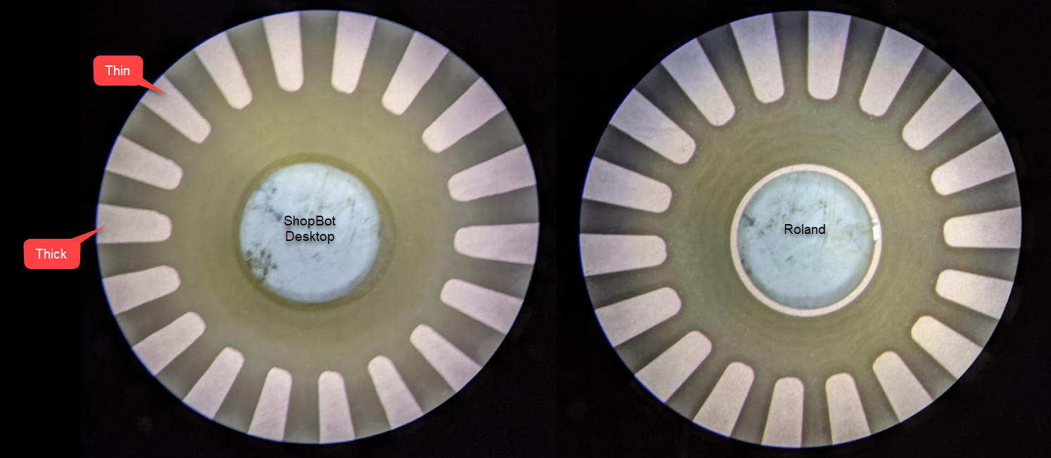
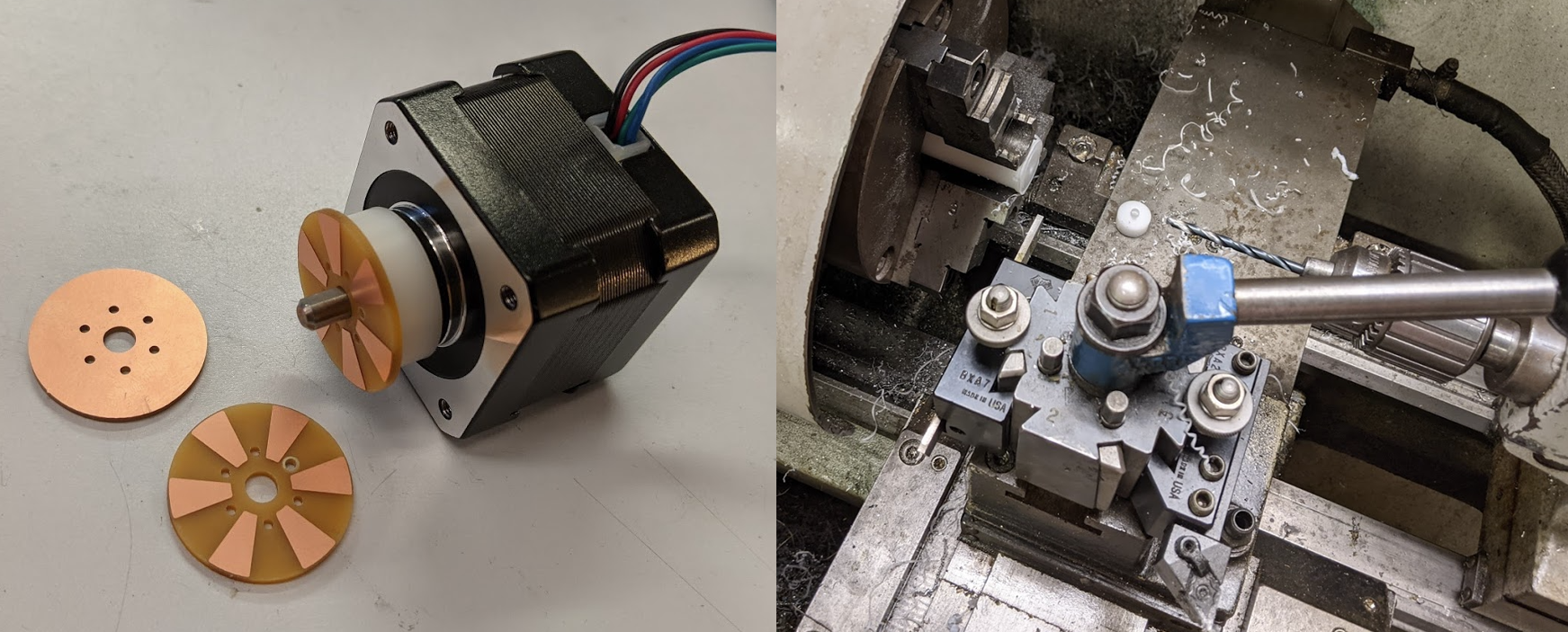
In machining the smaller targets on the ShopBot Desktop, I noticed that some copper pads appears significantly smaller than others. I confirmed this under a microscope with ImageJ, so machined a last minute replacement on the Roland with much better results. You can see the comparison of the two in the image below. Given this confirmation, I am intending to move my PCB milling operations to the Roland, which showed some really impressive results.
[ ]
]
Accuracy
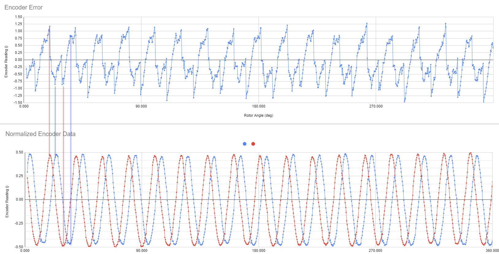
From the plots below, it would appear that I am acheiving about +/- 1.25deg of accuracy without calibration. On paper this is much worse than I was hoping for. With a 1.8deg step size for a stepper, acheiving at least 25% accuracy of a full step would be critical, so closer to +/-0.5 deg accuracy. With that said if we look closer at the error data, it is clear that it's highly repetitive between pole pitches. This tells us what's already expected, which is that our accuracy is interpolation limited (on the sensor side). Our interpolation technique assumes a perfectly sinusoidal signal, which is not going to be the case given the physical parameters of the system, and so a calibration should be applied in the form of a lookup table to smooth out some of this error. I made a quick attempt at this in the "Calibrated" Error plot below, by simply taking the first pole transition and subtracting its error from the first and second pole pairs. I didn't have the data bandwidth to do this very well, but given how repeatable the error is, I suspect it should be possible to get that error down to below the 0.5 deg range, or closer to the +/- 0.25 deg error suggested by the repeatability plot.
It's worth noting that the AMT encoder that I am using as a reference is rated to 0.25 deg of accuracy. So we are definitely within the right order of magnitude for a commercial product. The spec is also ambiguous in that it doesn't specify a +/- or full scale accuracy, but I believe it's +/-.
[ ]
]
[ ]
]
[ ]
]
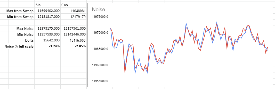
One big question I had was if EMF from the motor would manifest as noise at the sensor, which fortunately seems to not be the case at all. Noise levels did not change with the motor running or not running, and the error down to +/- 0.25 deg appears highly repeatable. To test this, I ran the motor through a full 720 deg sweep, and then took the difference between errors in the first and second revolution, by manually lining up the data. Ignore the +0.25 deg offset, as that's just a result of my lining things up poorly.

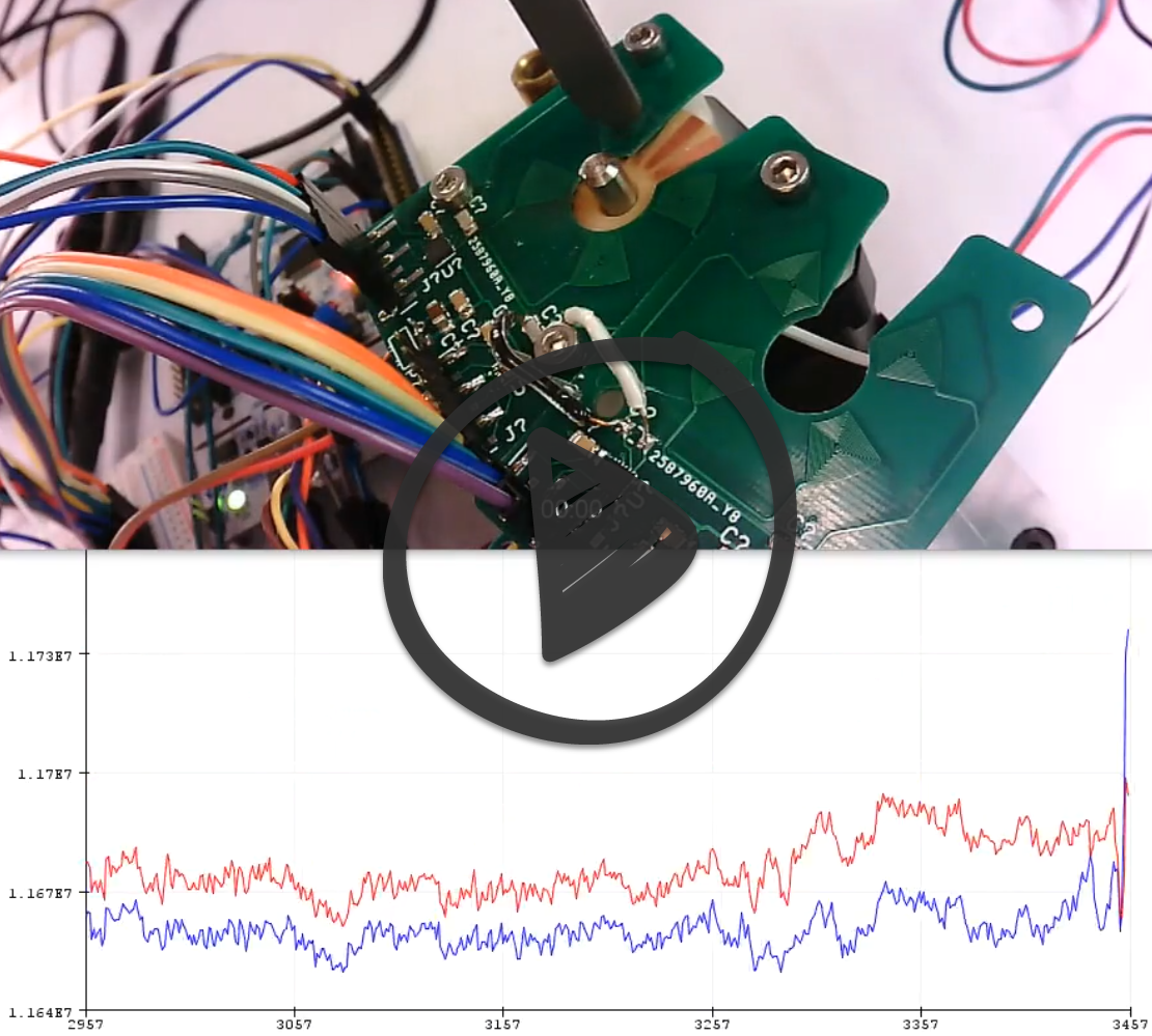
I definitely beleive there's some sort of potential for cross talk between the two sensors on the board, as with larger target spacing distances there would be bizzare artifacts at frequency inflection points, when both sensors approached the same value. You can see that shown in the screenshot below to a mild extent, but I unfortunately deleted some captures that showed the issue much worse at greater air gap thicknesses.
[ ]
]
With respect to speed, my SPI bus is clocked at only 3MHz, and transactions are currently taking 50us to transfer two 24 bit integers on a single SPI line. With a 50us transaction, I am able to resolve new rotor angles at 20kHz. A few steps I will take to increase speed are to break out each sensor onto its own SPI bus, which halves the total communication time. I can also increase the SPI bus to 8MHz, and chop off some of the dead time between bits and chip select lines. At the end of the day I believe it should be possible to increase the angular position refresh rate to closer/above 50kHz, which would correspond to a well commutated stepper motor spinning at 15kRPM. This is well above what any stepper is capable of, so this bandwidth is more useful for BLDCs, where with a larger pole pitch this bandwidth should allow for smooth commutation into the upper 10k's.
[![]() ]
]
HTMSTMAA Week 11 - 5/20/21
I spent the majority of this week (and last) stuck in debugging world with the encoder peroject. I actually only got everything back up and running last night, so my documentation is a little rushed here.
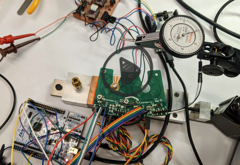
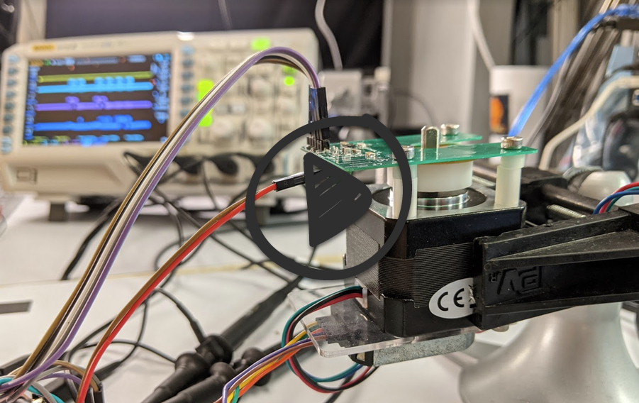
Below is a video of the system working. The motor I am attached to is unpowered, so I have been spinning it with a pair of vice grips, while trying to keep the jaws far enough away from the PCB to create noise. The motor is dual shafted, so on the top is the inductive encoder, and on the bottom is the CUI AMT102-V, which is a capacative, quadrature, through-shaft encoder that provides a total of 13 bits of noise free rotary position data (so 0.044 deg of resolution). I also considered just powering on the stepper and sweeping through full steps to normalize my encoder data, but have heard steppers can be trusted to +/-5% (which honestly seems quite conservative considering they're just stamped steel). In the end I also wanted to try and configure a quadrature decoder hardware peripheral on an ST micro, which was exciting and simple to get up and running, so I went with the designated encoder.
With both encoders, I can now plot my dubious encoder data against a known source, and begin to get an idea for how linear/sinusoidal my signal is, how repeatable it is peak to peak (remember this is a 6 pole encoder that was machined on a desktop router), and start to see what I am up against in terms of calibration. The results aren't quite as clean as I was hoping, but all of the makings of a solid encoder are there.

If you look at the top (normalzied) and bottom (plotted against time) data you can see the importance of our reference encoder to really understand the accuracy of the system. The bottom plot is just the encoder readout plotted against time, and so there's a stretch at the beginning where I wasn't rotating the shaft + visible changes in pitch from my inadvertent speeding up or slowing down rotation. This is not at all going to be a sin-cos encoder, and instead looks much more like a piecewise triangle wave. I think this is a good thing, considering that more linear the data results in a more constant (and overall higher magnitude) encoder response for a given rotation angle. The caveat is that I won't be able to use the straightforward arctan trick to linearize my two signals, and instead will likely need to go straight to a lookup table off of a calibration.
HTMSTMAA Week 9 - 5/5/21
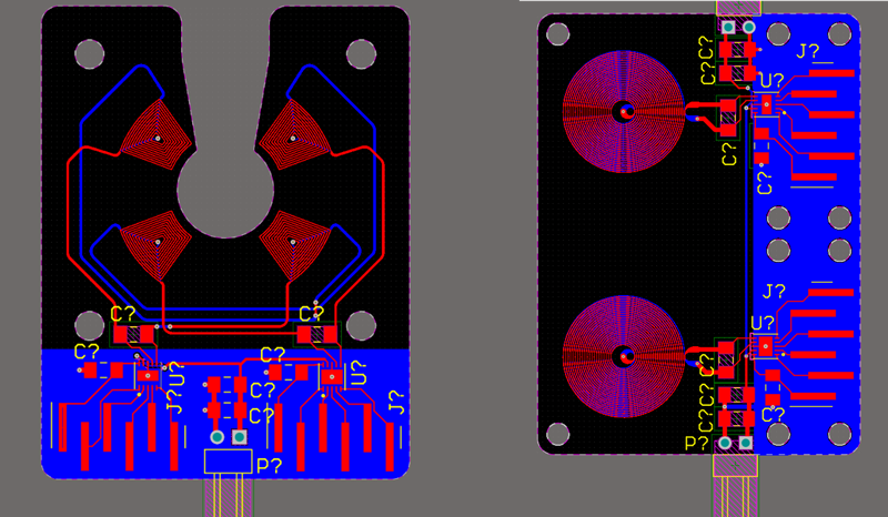
This week I designed (and ordered) two encoders built around the LDC1101, one is linear and one is rotary. Rather than try and integrate everything with an MCU at this stage, I went ahead and just broke out all of the necessary communication pins, similar to my last board, but this time with the LC tank fully integrated. Not a whole lot to say here until the boards come in and I can test them. In the meantime I have been searching for a suitable ADC replacement for the HX711 back over on the dynamometer project. It would be great to have an infrastructure for high resolution + gain analog signal measurement for a number of projects, this one included potentially.
I machined three rotors to test with, one is a single sided PCB with equal sized copper and copperless targets for sensing, the other is the same targets but with full copper on the back of the PCB (it's 1.6mm and I am imagining the copper on the back might be useful as shielding for outside noise in some applications). The third has 10% smaller copper target area, which might be helpful considering the coil's flux path is much larger than just the immediate area in front of the coil, and the smaller copper area might result in greater deltas between Rp_max and Rp_min.
The image below links to a video of the target mounted with under 10um of perpindicularity error between the target and the motor's rotational axis (that's 5/10's per division on the indicator). 10um is very measurable for the LDC1101, but due to the nature of the encoder it should be cancelled out for the most part. After I get some initial data I will deliberately push it out of perpindicularity and see how sensitive we are to that spec, but for now I am trying to have everything optimally dialed in.

And here's another video showing the first step of sweeping the turned delrin encoder mount that's sitting underneath the rotor. It took some adjusting with a flathead screwdriver to dial it into under 10um error, but seems stable and should be fine for initial testing despite just being a press fit at the moment.
Parameter Testing
Before mounting and testing the encoder I wanted to test some parameters of the new coils (inductance, quality factor, and ESR) which are important for properly configuring the encoder. I was able to borrow an impedance analyzer from Signal Kinetics for the day and was able to do these measurements, although strangely was seeing an order of magnitude change in inductance when measuring at 10kHz and 200kHz. To sanity check this I measured an OTS wire wound surface mount inductance rated at 10uH which measured spot on at 10.028uH and 10kHz and 10.071uH at 200kHz, so something is definitely amiss and I still haven't quite figured it out.
It's worth noting that inductance numbers for my coils were definitely asymptoting off around 200kHz. For example here are three inductances measured at three different frequencies, both with min target interaction:
- At 50kHz - 17.768 uH
- At 150kHz - 1.133 uH
- At 200kHz - 1.044 uH
Two explanations I thought of for frequency dependant inductance could be:
- Because the coils are unshielded (unlike the SM component) at high frequencies we are casting flux further and therefore being more effected by pieces of metal on the order of 10's of mms away. *Later I seem to have disproved this by introducing larger pieces of metal around the coils at and not seeing appreciable changes in inductance between frequencies.
- Because the top and bottom coils are only 0.8mm apart and highly parallel, at higher frequencies we are getting more of an effective parallel plate capacitor effect (although this also doesn't seem correct as you think the capacatance effects would start to dominate at higher frequencies and cause more delta and less asymptoting).
I also experimented with just measuring Rp directly, which the impedance analyzer I had accesss to allowed. The problem here was that I am limited to 200kHz peak frequency by the analyzer, and so I would have to interpolate way into higher frequency space with what's behaving (at least < 200kHz) as a second order polynomial, and I think that skin effect starts going off and doing nonlinear stuff at higher frequency, so I don't think the interpolation shown below is really safe to use.

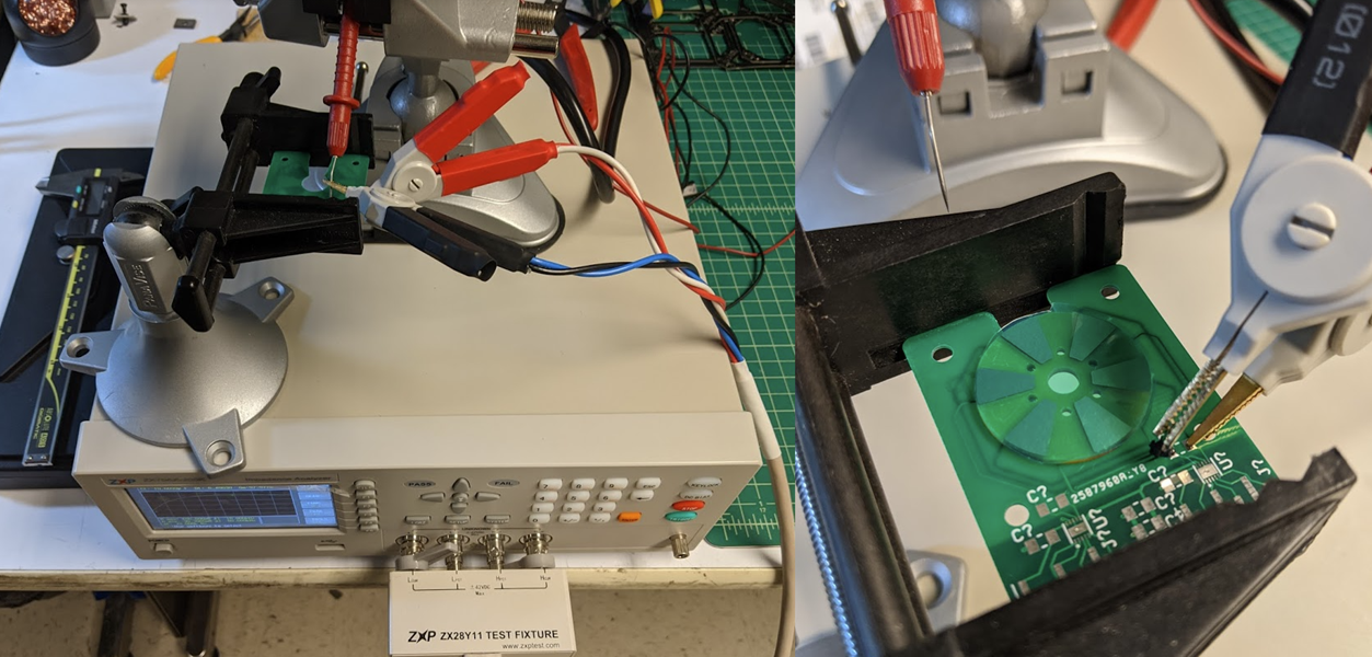
And lastly below is a picture of the encoder setup for the most part (I was soldering on different caps so wound up removing one of the screws that's in the way). It appears I have 26105 ticks of resolution, but am still sorting through parameter tuning necessary to bump that off and starting to trade some it in for SPS.

HTMSTMAA Week 8 - 4/22/21
This week I managed to get the LDC1101 configured and up and running, and in the process switched over to an STM32L432KC in Nucleo form, which is a cortex M4 clocked at 80 MHz with an FPU, and most importantly gives straightforward access to timer peripherals (my struggle last week was that after configuring a timer on the Feather M4, it seemed to promply get overwritten by Arduino's USB peripheral). Ultimately this will make more sense considering I would like to integrate this sensor into a closed loop stepper driver that I also built on ST hardware.
ST micros require an ST-Link for programming and debugging, which is a dedicated programmer with their own M0 MCU on board. For their lines of pre-broken-out microcontrollers (Nucelos or Discovery Boards), akin to what we all think of as an Arduino, they supply an on-board version of the ST-link, often with break-away tabs. They make it simple to perform in-line debugging with breakpoints, but if you want to actually start reading out data in real-time, the simplest way to do it is actually to talk with the St-Link over UART. It took me a while to figure this all out, but Here's an excellent + straightforward guide to getting serial communication up and running if you're curious.
Here's a link to the sensor up and running. It's incredibly sensitive (24 bits) and for context is resolving the motion of an aluminum plate attached to that stage, at 25um / revolution, so should be easily into nanometer range. The sensor is also far from configured properly, and allows for plenty of swapping between resolution, peak measuring range, and refresh rate. Lots of work left to do towards this end!
And lastly here's the actual frequency response of the LC circuit changing as a large chunk of aluminum is brought over the coil It's hard to make out, but it's varying between 1.4 and 1.6 MHz, where frequency increases with the presence of aluminum. Steel had a similar, but slightly less prominent response (although the two pieces of metal were very different sizes so don't read into that too much). The steel target also reduced the amplitude of the response, and yielded cleaner, presumably less noisy oscilations.

For next week, here's a nice blog post I found about speeding up HAL's SPI transactions. One good reason to prefer ST to Atmel/Microchip here is that CubeMX generates MCU-specific initialization code, and actually going in to speed things up involves appreciably less searching for registers in datasheets.
HTMSTMAA Week 7 - 4/15/21
This week I switched gears from working on the dynamometer and set out to start communicating with the LDC1101 from TI. The LDC1101 is an inductive to digital converter that uses an external LC tank circuit to measure changes in impedance (Rp measurement mode) or resonant frequency (LHC mode) of the oscillator, relative to the change in presence of conductive or magnetically permeable materials respectively. Despite the existence of plenty of inductive to digital converters on the market (many of which are 2 or 4 channel devices in a single package), the LDC1101 is the only one I could find that uses SPI, and has a sample rate fast enough for high speed rotary encoding. These encoders are a bit of a bear to configure, and require multiple spreadsheets and a pretty thorough read through the datasheet. With that said, there aren't many other sensing options that provide 24 bits with noise this low, and with SPS + communication this fast.
Over IAP I put together a closed loop stepper driver using the TMAG5170 (a 3-axis hall effect sensor) in place of the popular AMS hall effect sensors. Ultimately that sensor's SNR was just high enough to prevent resolving more than two positions between 1.9 deg full steps, while also being speed limited in terms of update rate. While this sensor will ultimately live on the back of that board, for a first pass on starting communication, I designed and machined a simple breakout board in Altium, and milled it in house.

Because I have been programming so much on the SAMD51 lately, I figured I would go ahead and do a first pass communicating with the board on that micro. The LDC1101 requires a high frequency (in the MHz with a recommended value of 16MHz) external clock signal for LHC measurement, to serve as a reference when counting oscillations of the tank circuit. I reused some of the dyno code and adjusted it to run at 50% duty cycle at 15MHz as shown below, keep in mind TC4 is a 120MHz clock. This did require some digging through the datasheet, and I ultimately discovered the period register which was relevant after switching from NPWM WAVEGEN mode to NFRQ. With a working 15MHz CLKIN signal I started probing the LHC data registers which were all returning zero.
TC4->COUNT8.CTRLA.reg = TC_CTRLA_MODE_COUNT8 | TC_CTRLA_PRESCALER_DIV1 | TC_CTRLA_PRESCSYNC_GCLK;
TC4->COUNT8.WAVE.reg = TC_WAVE_WAVEGEN_NFRQ;
TC4->COUNT8.PER.bit.PER = 3;
After more snooping around with a scope, it appears that my clock is turning off after I open up USB communication, which is bizarre considering I wasn't seeing this happening with the dyno. That's as far as I got this week, but I do plan to double back and investigate if that timer is also turning during serial communication for the dyno (this would be bad considering it determines back torque on the motor, which I am very reliant on being steady during sweeps). For this project, considering I am not relying on any external libraries, I will switch over to an STM32 micro (also what I've used for the closed loop stepper driver that this will ultimately be implemented on).
