Inductive Encoder
HTMSTMAA Week 9 - 5/5/21
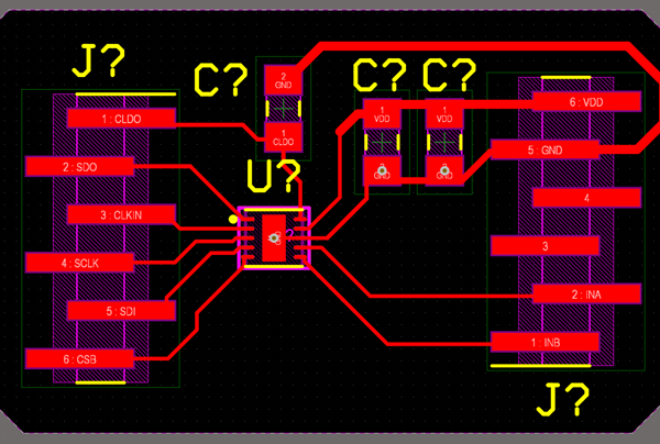
This week I designed (and ordered) two encoders built around the LDC1101, one is linear and one is rotary. Rather than try and integrate everything with an MCU at this stage, I went ahead and just broke out all of the necessary communication pins, similar to my last board, but this time with the LC tank fully integrated. Not a whole lot to say here until the boards come in and I can test them. In the meantime I have been searching for a suitable ADC replacement for the HX711 back over on the dynamometer project. It would be great to have an infrastructure for high resolution + gain analog signal measurement for a number of projects, this one included potentially.
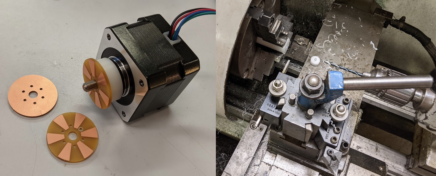
I machined three rotors to test with, one is a single sided PCB with equal sized copper and copperless targets for sensing, the other is the same targets but with full copper on the back of the PCB (it's 1.6mm and I am imagining the copper on the back might be useful as shielding for outside noise in some applications). The third has 10% smaller copper target area, which might be helpful considering the coil's flux path is much larger than just the immediate area in front of the coil, and the smaller copper area might result in greater deltas between Rp_max and Rp_min.
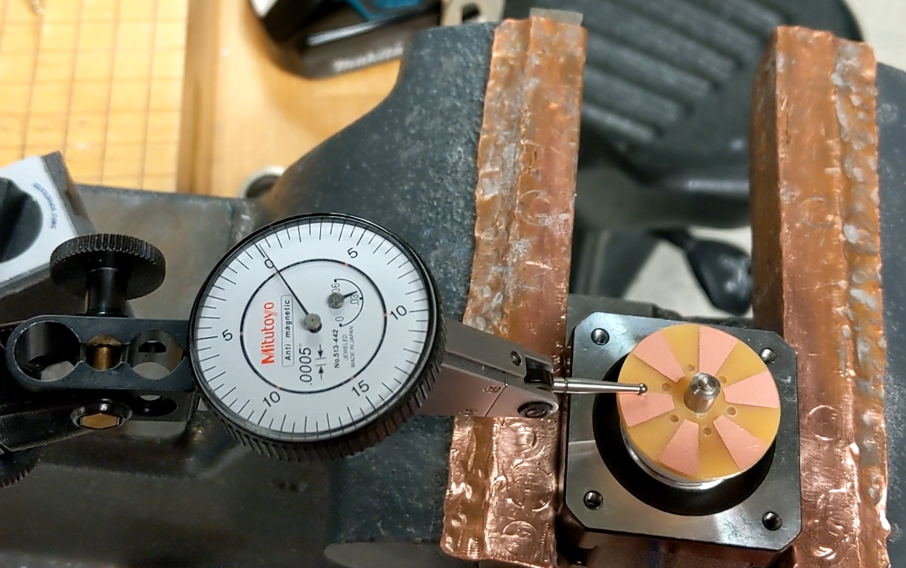
The image below links to a video of the target mounted with under 10um of perpindicularity error between the target and the motor's rotational axis (that's 5/10's per division on the indicator). 10um is very measurable for the LDC1101, but due to the nature of the encoder it should be cancelled out for the most part. After I get some initial data I will deliberately push it out of perpindicularity and see how sensitive we are to that spec, but for now I am trying to have everything optimally dialed in.
HTMSTMAA Week 8 - 4/22/21
This week I managed to get the LDC1101 configured and up and running, and in the process switched over to an STM32L432KC in Nucleo form, which is a cortex M4 clocked at 80 MHz with an FPU, and most importantly gives straightforward access to timer peripherals (my struggle last week was that after configuring a timer on the Feather M4, it seemed to promply get overwritten by Arduino's USB peripheral). Ultimately this will make more sense considering I would like to integrate this sensor into a closed loop stepper driver that I also built on ST hardware.
ST micros require an ST-Link for programming and debugging, which is a dedicated programmer with their own M0 MCU on board. For their lines of pre-broken-out microcontrollers (Nucelos or Discovery Boards), akin to what we all think of as an Arduino, they supply an on-board version of the ST-link, often with break-away tabs. They make it simple to perform in-line debugging with breakpoints, but if you want to actually start reading out data in real-time, the simplest way to do it is actually to talk with the St-Link over UART. It took me a while to figure this all out, but Here's an excellent + straightforward guide to getting serial communication up and running if you're curious.
Here's a link to the sensor up and running. It's incredibly sensitive (24 bits) and for context is resolving the motion of an aluminum plate attached to that stage, at 25um / revolution, so should be easily into nanometer range. The sensor is also far from configured properly, and allows for plenty of swapping between resolution, peak measuring range, and refresh rate. Lots of work left to do towards this end!
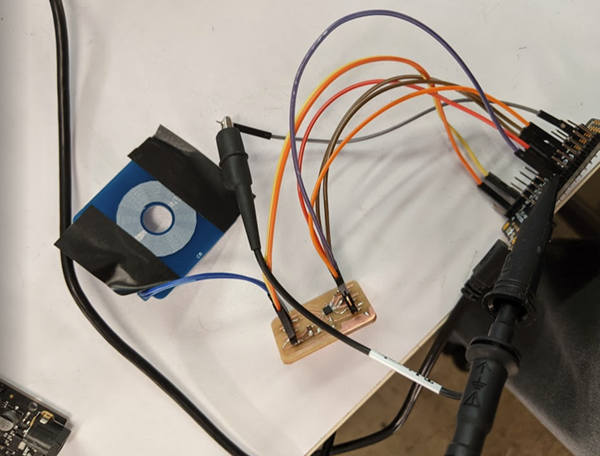
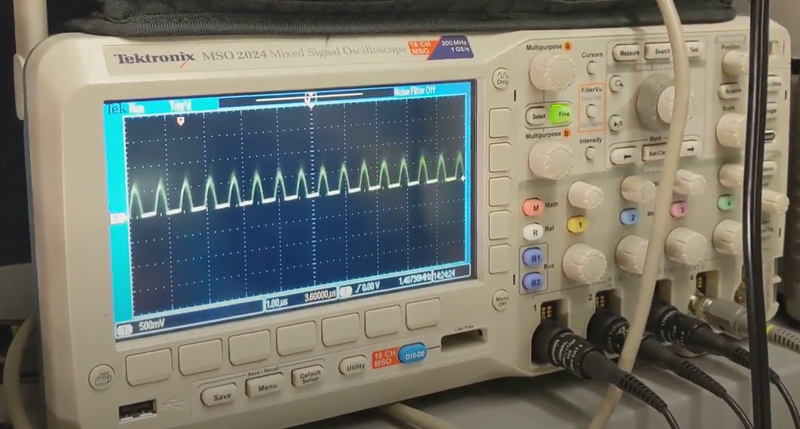
And lastly here's the actual frequency response of the LC circuit changing as a large chunk of aluminum is brought over the coil It's hard to make out, but it's varying between 1.4 and 1.6 MHz, where frequency increases with the presence of aluminum. Steel had a similar, but slightly less prominent response (although the two pieces of metal were very different sizes so don't read into that too much). The steel target also reduced the amplitude of the response, and yielded cleaner, presumably less noisy oscilations.
For next week, here's a nice blog post I found about speeding up HAL's SPI transactions. One good reason to prefer ST to Atmel/Microchip here is that CubeMX generates MCU-specific initialization code, and actually going in to speed things up involves appreciably less searching for registers in datasheets.
HTMSTMAA Week 7 - 4/15/21
This week I switched gears from working on the dynamometer and set out to start communicating with the LDC1101 from TI. The LDC1101 is an inductive to digital converter that uses an external LC tank circuit to measure changes in impedance (Rp measurement mode) or resonant frequency (LHC mode) of the oscillator, relative to the change in presence of conductive or magnetically permeable materials respectively. Despite the existence of plenty of inductive to digital converters on the market (many of which are 2 or 4 channel devices in a single package), the LDC1101 is the only one I could find that uses SPI, and has a sample rate fast enough for high speed rotary encoding. These encoders are a bit of a bear to configure, and require multiple spreadsheets and a pretty thorough read through the datasheet. With that said, there aren't many other sensing options that provide 24 bits with noise this low, and with SPS + communication this fast.
Over IAP I put together a closed loop stepper driver using the TMAG5170 (a 3-axis hall effect sensor) in place of the popular AMS hall effect sensors. Ultimately that sensor's SNR was just high enough to prevent resolving more than two positions between 1.9 deg full steps, while also being speed limited in terms of update rate. While this sensor will ultimately live on the back of that board, for a first pass on starting communication, I designed and machined a simple breakout board in Altium, and milled it in house.
Because I have been programming so much on the SAMD51 lately, I figured I would go ahead and do a first pass communicating with the board on that micro. The LDC1101 requires a high frequency (in the MHz with a recommended value of 16MHz) external clock signal for LHC measurement, to serve as a reference when counting oscillations of the tank circuit. I reused some of the dyno code and adjusted it to run at 50% duty cycle at 15MHz as shown below, keep in mind TC4 is a 120MHz clock. This did require some digging through the datasheet, and I ultimately discovered the period register which was relevant after switching from NPWM WAVEGEN mode to NFRQ. With a working 15MHz CLKIN signal I started probing the LHC data registers which were all returning zero.
TC4->COUNT8.CTRLA.reg = TC_CTRLA_MODE_COUNT8 | TC_CTRLA_PRESCALER_DIV1 | TC_CTRLA_PRESCSYNC_GCLK;
TC4->COUNT8.WAVE.reg = TC_WAVE_WAVEGEN_NFRQ;
TC4->COUNT8.PER.bit.PER = 3;
After more snooping around with a scope, it appears that my clock is turning off after I open up USB communication, which is bizarre considering I wasn't seeing this happening with the dyno. That's as far as I got this week, but I do plan to double back and investigate if that timer is also turning during serial communication for the dyno (this would be bad considering it determines back torque on the motor, which I am very reliant on being steady during sweeps). For this project, considering I am not relying on any external libraries, I will switch over to an STM32 micro (also what I've used for the closed loop stepper driver that this will ultimately be implemented on).